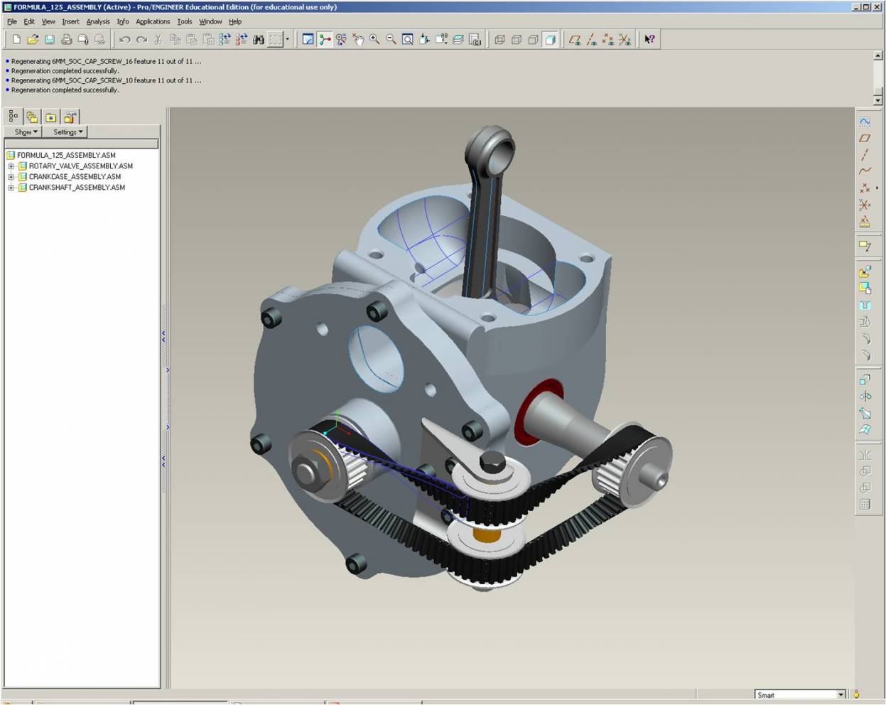
Here are some Interview Questions for Mechanical Engineer Students
1. What are the different types of fits? Explain?
On the basis of Indian standards fits can mainly be categorized into
three groups: > Clearance Fit: These types of fits are characterized
by the occurrence of a clearance between the two mating parts. The
difference between the minimum size of the hole and the maximum size of
the shaft is called the minimum clearance, the difference between the
maximum size of the hole and the minimum size of the shaft is known as
maximum clearance.
>
Interference Fit: In these types of fits the size of the mating
parts are predefined so that interference between them always occurs.
The tolerance zone of the hole is completely below the tolerance zone of
the shaft. > Transition Fit: As the name suggests these type of fit
has its mating parts sized limited to allow either clearance or
interference. The tolerance zone of the hole and the shaft overlaps in
case of such fits.
For a shaft designated as 40 H8/f7, calculate the tolerances.
Given: Shaft designation = 40 H8/f7 The shaft designation 40 H8/f 7
means that the basic size is 40 mm and the tolerance grade for the hole
is 8 ( i. e. I T 8) and for the shaft is 7 ( i. e. I T 7). Since 40 mm
lies in the diameter steps of 30 to 50 mm, therefore the geometric mean
diameter, D = Square root of (30 x 50) = 38.73 mm We know that standard
tolerance unit, i = 0.45 x Cube root of (D) + 0.001 D i = 0.45 × 3.38 +
0.03873 = 1.559 73 or 1.56 microns i = 1.56 × 0.001 = 0.001 56 mm …(1
micron = 0.001 mm) The standard tolerance for the hole of grade 8 (IT8) =
25 i = 25 × 0.001 56 = 0.039 mm The standard tolerance for the shaft of
grade 7 (IT7) = 16 i = 16 × 0.001 56 = 0.025 mm
What are the factors that can affect the Factor of safety selection?
The factor of safety is used in designing a machine component. Prior to
selecting the correct factor of safety certain points must be taken into
consideration such as: > The properties of the material used for the
machine and the changes in its intrinsic properties over the time
period of service. > The accuracy and authenticity of test results to
the actual machine parts. > The applied load reliability. > The
limit of stresses (localized). > The loss of property and life in
case of failures. > The limit of initial stresses at the time period
of manufacture. > The extent to which the assumptions can be
simplified. The factor of safety also depends on numerous other
considerations such as the material, the method of manufacturing , the
various types of stress, the part shapes etc.
2. What is heat treatment and why is it done?
Heat treatment can be defined as a combination of processes or
operations in which the heating and cooling of a metal or alloy is done
in order to obtain desirable characteristics without changing the
compositions. Some of the motives or purpose of heat treatment are as
follows: > In order to improve the hardness of metals. > For the
softening of the metal. > In order to improve the machinability of
the metal.
> To change the grain size. > To provide better resistance to heat, corrosion, wear etc.
Heat treatment is generally performed in the following ways: >
Normalizing > Annealing > Spheroidising > Hardening >
Tempering > Surface or case hardening
3. What are the rules that must be kept in mind while designing castings?
Some of the points that must be kept in mind during the process of cast
designing are as follows: > To avoid the concentration of stresses
sharp corners and frequent use of fillets should be avoided. >
Section thicknesses should be uniform as much as possible. For
variations it must be done gradually. > Abrupt changes in the
thickness should be avoided at all costs. > Simplicity is the key,
the casting should be designed as simple as possible. > It is
difficult to create true large spaces and henceforth large flat surfaces
must be avoided. > Webs and ribs used for stiffening in castings
should as minimal as possible. > Curved shapes can be used in order
to improve the stress handling of the cast.
4. What are the points that should be kept in mind during forging design?
Some of the points that should be followed while forging design are:
> A radial flow of grains or fibers must be achieved in the forged
components. > The forged items such as drop and press forgings should
have a parting line that should divide the forging into two equal
halves. > The ribs in a forging should not be high or thin. > In
order to avoid increased die wear the pockets and recesses in forgings
should be minimum. > In forgings the parting line of it should lie as
far as possible in a single plane. > For ease of forging and easy
removal of forgings the surfaces of the metal should contain sufficient
drafts.
5. Describe briefly the different cold drawing processes.
Some of the important cold drawing processes are as follows: > Bar
and Rod Drawing: In the case of bar drawing the hot drawn bars are at
first pickled, washed and coated to prevent oxidation. Once this is done
a draw bench is used for the process of cold drawing. In order to make
an end possible to enter a drawing die the diameter of the rod is
reduced by the swaging operation. This end is fastened by chains to the
draw bench and the end is gripped by the jaws of the carriage. In this
method a high surface finish and accuracy dimensionally is obtained. The
products of this process can be used directly without any further
machining. > Wire Drawing: Similar to the above process the bars are
first pickled, washed and coated to prevent any oxidation. After this
the rods are passed through several dies of decreasing diameter to
provide a desired reduction in the size ( diameter ). The dies used for
the reduction process is generally made up of carbide materials.
6. What are the different theories of failure under static load, explain briefly?
The main theories of failure of a member subjected to bi-axial stress
are as follows: > Maximum principal stress theory ( Rankine’s
theory): This theory states that failure occurs at a point in member
where the maximum principal or normal stress in a bi-axial system
reaches the maximum strength in a simple tension test. > Maximum
shear stress theory ( Guest’s or Tresca’s theory): This theory states
that failure occurs when the biaxial stress reaches a value equal to the
shear stress at yield point in a simple tension test. > Maximum
principal strain theory ( Saint Venant theory): This theory states that
failure occurs when bi-axial stress reaches the limiting value of
strain. > Maximum strain energy theory ( Haigh’s theory): This theory
states that failure occurs when strain energy per unit volume of the
stress system reaches the limiting strain energy point. > Maximum
distortion energy theory ( Hencky and Von Mises theory): This theory
states that failure occurs when strain energy per unit volume reaches
the limiting distortion energy.
7. What are the assumptions made in simple theory of bending?
The assumptions made in the theory of simple bending are: > The
material of the beam is homogeneous this implies that it is uniform in
density, strength and have isotropic properties meaning possessing same
elastic property in all directions. > Even after bending the cross
section of the beam remains constant. > During the initial stages the
beam is straight and unstressed. > All the stresses in the beam are
within the elastic limit of its material. > The layers of the beam
are free to contract and expand longitudinally and laterally > On any
cross section the perpendicular resultant force of the beam is zero.
> Compared to the cross-sectional dimension of the beam the radius of
curvature is very large.
8. Why is stress considered important in a shaft?
The following types of stresses are prevalent in shafts: > At the
outermost surface of the shaft the max shear stress occurs on the
cross-section of the shaft. > At the surface of the shaft on the
longitudinal planes through the axis of the shaft the maximum
longitudinal shear stress occurs. > At 45 degrees to the maximum
shearing stress planes at the surface of the shafts the major principal
stress occurs. It equals the max shear stress on the cross section of
the shaft. > For certain materials where the tensile and compressive
strengths are lower in measure as compared to the shear strength, then
the shaft designing should be carried out for the lowest strengths. >
All these stresses are of significance as they play a role in governing
the failure of the shaft. All theses stresses get generated
simultaneously and hence should be considered for designing purposes
Follow the blog to get more updates
Learn pro-E faster and easier. To know more
click here